I often follow the functional core, imperative shell way of constructing software:
- Isolate business logic into a set of pure functions (the functional core).
- Implement side-effects and mutable state in a thin layer around the core (the imperative shell).
This not only shapes how I write code, but also how I think. When designing a software system, I’ll assume the functional core and the imperative shell are independent. This allows me to ignore servers, storage, networks, and other technical constraints when starting out.
Instead, I can focus on data and functions in the abstract, which are (by definition) enough to describe the functional core of the system: What needs to be computed, and from what? What intermediary data and functions can I anticipate?
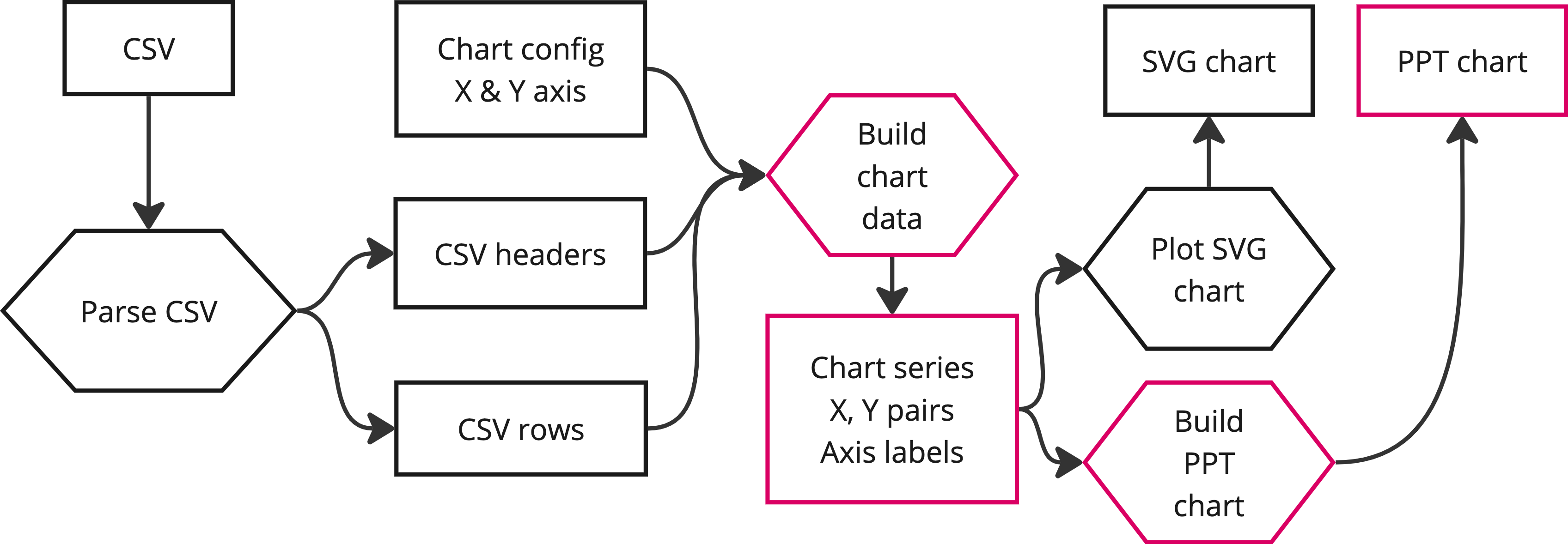
I’ve found drawing the flow of data types through the functional core to yield useful system diagrams. For example:

This article illustrates the properties and use of these functional core diagrams.
(I’m probably reinventing some wheel here. So far, I haven’t found a diagram type with the nuance I’m looking for. A data-flow diagram comes close, but it’s a bit too rigid. If you can think of something, let me know!)
Definition
A functional core diagram (FCD) is a directed graph with two kinds of nodes:
- Types
- Functions
An FCD allows the following edges:
- Arguments: Types point to functions accepting them.
- Results: Functions point to their return types.
- Subtypes: Types point to their subtypes (if any).
Types and functions are abstract. They need not reflect a concrete implementation, but should have clear semantics.
I use rectangles for types, and hexagons for functions, but any distinct shapes work. Types are in noun-form, functions are in verb-form. Colorings may group types and/or functions.
Usage
I use FCDs to explore potential layouts for a software system. I start with known inputs and outputs and connect the gaps with (abstract) functions and intermediary types, until I’m confident the design is sound.
While drawing candidate diagrams, I’ll look out for various system properties:
- Dependencies
- Coupling
- Module boundaries
- Transaction boundaries
- Standard data types
- Opportunities for caching
- Opportunities for concurrency
- Hot paths
- etc.
When I identify a problem (e.g. unnecessary coupling) I’ll try to refactor the FCD, almost like code. In that sense, FCDs are like graphical pseudo-code.
For example, the introductory diagram can be refactored to be less coupled to the CSV format, and support additional output formats:

Notice how the new type for chart series emerges as a natural boundary, something immediately visible in the FCD. (Adding support for more input types is left as an exercise for the reader.)
It’s hard to pin down the list of things to look out for, or when and why to refactor. Like with many skills, it takes a bit of practice to build an intuition and get good results.
Colorings
I use colorings to group types and functions by various properties. For example:
- Which module is responsible for which function?
- Which data needs to be persistent?
- Which workloads belong on the server-side, which can be run client-side?
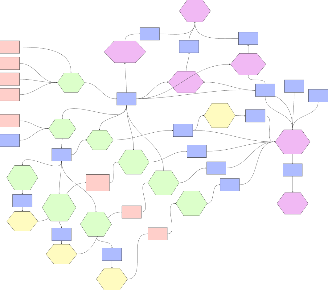
The following is a real-world FCD with a coloring specifying where to implement functions in a service-oriented architecture (labels removed):

Discovering the dependency on the yellow function in the upper right early saved us from a difficult refactoring later on.
Abstraction
FCDs allow abstraction and imprecision by design. For example, listing all inputs and outputs of a system and connecting them by one big function is a valid FCD, however useful. On the other hand, an FCD laying out every type and every function of a concrete implementation is probably too granular.
Being able to explore this “search space” graphically feels both natural and powerful. Finding the right level of abstraction is key—just enough depth that I can confidently explain the system to myself and others, but not more.
Limitations
Not all system designs benefit from an FCD. For example, systems where efficient I/O is an inherent goal (e.g. databases, video streaming, etc.) often have a shallow functional core, and the design problems are found in concrete technology or infrastructure.
FCDs don’t capture choice, temporal order, or relations between types. For these purposes, consider activity diagrams, sequence diagrams or entity relationship diagrams.
Finally, functional cores are generally not independent from imperative shells. At some point, we have to invite the real world in (computers, memory limits, networks, etc.) and may have to adjust our functional core to fit these constraints.
(Incidentally, the moment when I have to adapt an otherwise ideal functional core to fit the real world has become my definition of accidental complexity.)
Conclusion
FCDs are no silver bullet, but I often find drawing the functional core of a system a worthwhile exercise. Most of all, I enjoy the organic construction of FCDs: I can start with a diagram as simple as one big function, and refactor it until I’m satisfied with the level of detail.
I suspect there are some fundamental properties making FCDs effective (category theory comes to mind). In any case, I hope I was able to present FCDs as a practical, useful tool for system design. ∎